
 Test Challenge
For single-technology, single-wavelength PON deployments, the simple broadband power meter has been an excellent and sufficient tool for PON activation and troubleshooting. However, the existing PON fiber infrastructure can carry light power across many wavelengths simultaneously and— for all practical purposes—without interference. Based on this concept, new, next-generation PON technologies are being deployed on the same fiber plant as current-generation technologies but using independent wavelengths. Powerful new PON capabilities can thus be quickly rolled out to customers over the existing infrastructure by simply changing the equipment at the ends of the fiber.
However, the presence of multiple wavelengths on the same fiber or within the same PON infrastructure presents significant problems for those engaged with PON activation and troubleshooting and who are equipped with only broadband (unfiltered) optical power meters. There are two primary use cases where these problems will surface:
- In coexistent PON service structures where two PON services at different wavelengths are carried on the same fiber simultaneously, the use of a broadband power meter will result in erroneous and misleading power measurements as explained in more detail below.
- In parallel PON service structures where two services at different wavelengths exist in the same footprint, the network will be constructed such that a given fiber will carry either one service (wavelength) or the other but not both. In this use case, it is very easy to accidentally connect a customer to the wrong service through patching or provisioning errors. The use of a broadband power meter in this scenario runs the risk that power measured in the PON may seem good, but in reality, the wrong wavelength is being delivered. Unnecessary customer-premises equipment (CPE) swapping, long troubleshooting sessions, and needless escalations can result if you can’t immediately identify the simple fact that the wrong wavelength is present at the customer premise.
Inside an Optical Power Meter
Optical power meters employ photodiodes that detect the number of photons striking the photodiode surface per unit of time and convert that photonic rate into a measured light power. The photodiodes in most broadband power meters can detect light energy across a broad spectrum of wavelengths, normally between 780 nm and 1650 nm. Power meters constructed in this way will measure photonic energy from any and all wavelengths of light within the photodiode’s wavelength range and will produce a single power measurement proportional to the sum of all photons from all wavelengths per unit of time. (See Figure 1)
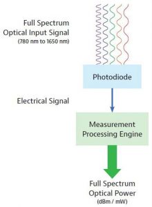
Fig.1. Power meters constructed in this way will measure photonic energy from any and all wavelengths of light within the photodiode’s wavelength range and will produce a single powermeasurement proportional to the sum of all photons from all wavelengths per unit time.
As a specific example, if a broadband power meter is used to measure a PON with coexistent GPON (1490 nm) and XGSPON (1577 nm) services, the output of the broadband power meter will be the sum of the powers of both the GPON and XGS-PON wavelengths. The user will have no idea what the actual power and margin are for either of the two PON services on the link. Also important is the fact that even in networks that are intended to have a single service on the fiber at a time, a broadband power meter cannot tell you which service (wavelength) it is currently measuring. Errored provisioning and connection/patching will go undetected until the CPE fails to activate the service.
For these reasons, PON power meters designed for use in multi-service environments include optical filters in front of their internal photodiodes to ensure that only the power for a specific wavelength of interest is measured. In the case of PON power meters that are designed for GPON and XGS-PON (both coexistent and parallel networks), two filtered photodiodes are normally used. More specifically, the light from the measured fiber is split inside the power meter to two independent photodiodes, passing through two selective filters in front of those photodiodes. One filter is for GPON wavelength of 1490 nm, and the second filter is for XGS-PON, at 1577 nm. (See Figure 2)
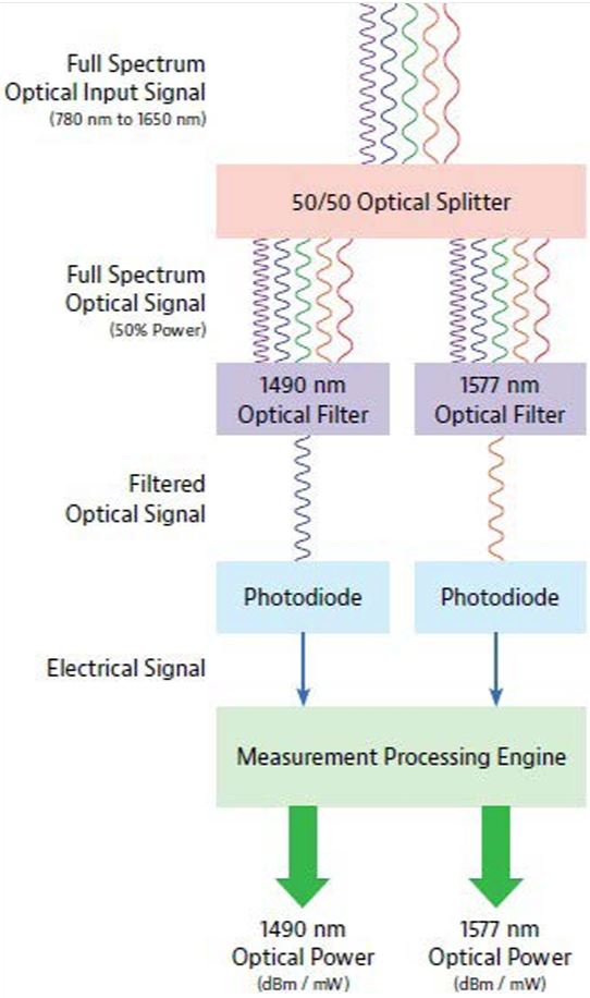
Fig. 2. One filter is for GPON wavelength of 1490nm, and the second filter is for XGS-PON, at 1577nm
PON power meters constructed as such can instantly and simultaneously measure the optical power for the filtered wavelengths accurately and independently, preventing the misleading measurements delivered by broadband power meters in a coexistent environment, and identifying the specific wavelengths associated with those power measurements for both coexistent and parallel PONs.
Consequences of Applying the Wrong Tool in a MultiService PON
As discussed above, when using a broadband power meter in a coexistent GPON / XGS-PON network, the measured power will appear artificially high when both GPON and XGS-PON signals are present on the fiber at the same time. This can have two types of impacts during service activation:
- Power measurement could look good, but the actual power of the individual GPON and XGSPON signals are too low to operate equipment, causing a false pass and driving:
- Unnecessary CPE swap-outs
- Troubleshooting complications, increasing the amount of time required to complete the installation
- Needless escalations
- Power measurement could measure too high, causing a false failure and driving:
- Unnecessary call-backs to the central office for incorrect requests for provisioning checks or changes
- Extensive time spent troubleshooting a problem that does not exist
- Unnecessary escalations and truck-rolls
In parallel, GPON / XGS-PON where network design intentionally routes either GPON or XGS-PON to the premise (but not both), using a broadband power meter could result in measuring good power at the end of the drop fiber without realizing that the wavelength associated with the power measurement is wrong. Something as simple as connecting to the wrong type of splitter in the splitter cabinet or connecting the drop fiber to the wrong drop terminal port can easily create such a scenario.
 More recently, miss-provisioned optical line terminal (OLT) ports are an increasing cause for the wrong wavelength appearing at the end of a customer’s drop. As PON OLT equipment has matured, there has been a natural migration from dedicated, single-service OLT ports to dual-function OLT ports (configurable as one service type or another), to multi-service OLT ports (providing simultaneous PON services and internal coexistence functions within the same OLT port).
Both provisioning and connection/patching errors will once again drive:
- Unnecessary CPE swap-outs
- Troubleshooting complications, increasing the amount of time required to complete the installation
- Unnecessary escalations and truck-rolls
Avoiding Cross-connection Issues
When a new customer signs up with a service provider they trigger several activities. The first steps include scheduling an installation date along with ordering the ONT and any other CPE. However, simply connecting any ONT to a live PON network does not ensure the activation of services. If that were the case anyone could purchase an ONU and connect it to get service for free.
The other step that happens is telling an OLT that it will be responsible for and approved to deliver services to a specific ONT device. This is referred to as provisioning the service, meaning that a specific OLT port is assigned to provide support (data) to a specific ONT serial number.
If you connect the ONT to the correct drop terminal port, which routes back to the OLT port where the service has been provisioned, then the service will turn up as it should. However, if you connect to the wrong drop terminal port and therefore an OLT port where the service has not been provisioned, the ONT may boot up but the service itself will not activate. This is because the OLT is expecting the ONT to appear or communicate on a different port, so it won’t deliver service to that ONT. Wrong light, i.e., a downstream wavelength from an OLT port where the service was not provisioned, is a fairly common problem with FTTx deployments.
 The drop terminal enclosure typically includes labeling to show which port is which, but in the real world it’s all too easy for labels to be illegible, missing, or wrong, often because the distribution fiber routing has been altered by a previous tech. To ensure the right fiber cable is connected to the right OLT port and to enable easy handling of installation error tickets, it requires a device that identifies the type of OLT and the OLT-ID at any network location.
This device must be able to evaluate the PON-ID, a unique identifier that is standardized by ITU-T and is a frame in PLOAMd carrying PON-specific information, such as OLTID, ODN class, and the transmitted optical level from the OLT. If you can extract and read it, you can compare the provisioning information and state for certain whether the OLT port a customer is connected to is the right one or not.
Addressing the Challenge
Field technicians need to quickly and accurately:
- Confirm that there is sufficient power to operate a resilient PON service
- Confirm that the measured power is on the correct wavelength for the desired service
- Segment problems down to a specific portion of the fiber plant, avoiding unnecessary CPE or drop fiber replacements, and increasing the accuracy of escalation calls
Conclusion
Next-generation PONs deliver many business-critical advantages to providers compared to current PON technologies, including higher service-rate offerings, improved service-rate symmetry, increased split ratios, and the convergence of multiple applications into a single optical distribution network (ODN). As many providers transition from BPON, GPON, or EPON to next-generation technologies like XGS-PON or NG-PON2, a new test paradigm is required, as the potential for negative business impacts associated with continued use of broadband power meters in a multiservice PON environment is a real and immediate concern.
However, by deploying selective PON power meters and TruePON testers for activation and repair of multi-service PONs, providers will improve the efficiency of service activation and repair groups, and avoid the increased costs associated with longer installation and troubleshooting times and unnecessary escalations and truck rolls.