
For several years, the optical fiber user community has been rapidly shifting from traditional singlemode fibers to new “Full Spectrum” singlemode fiber that meets the International Telecommunications Union (ITU-T) G.652D specification.
First off, these terms are important:
- RWP stands for Reduced Water Peak
- LWP stands for Low Water Peak
- ZWP stands for Zero Water Peak
- The ‘E band’ is the 1360-1460nm wavelength. The specific wavelength of 1383nm is referred to as “the water peak”
G.652 singlemode fiber, also known as standard single fiber, is the most commonly deployed singlemode fiber. It has four variations: G.652A, B, C, and D – and two classifications. The first classification is G.652.A and G.652.B fibers, these are designed to have a zero-dispersion wavelength near 1310nm and are optimized for operation in the 1310nm band. However, they are not suitable for applications in Wavelength Division Multiplexing (WDM) due to water peak. The more advanced classification of G.652.C and G.652.D fibers are optimized with a reduced water peak for spectrum operation, which allows them to be utilized in the wavelength region between 1310nm and 1550nm to support Coarse Wavelength Division Multiplexed (CWDM) transmission.
Comparing Conventional G.652.A/B with LWP fiber and ZWP fiber:
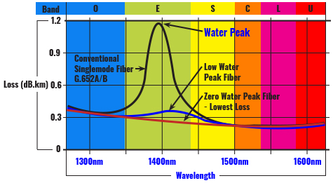
The ‘Water Peak’ can be seen at the 1383nm wavelength
These reduced water peak fibers are considered “full spectrum” because of the reduction of loss in the water absorption spectral region known as the E band (1360 – 1460nm), this allows transmission in this previously unusable portion of the wavelength spectrum.
While all RWP fibers have a lower loss in the E band, not all fibers are created equal. In fact, there are two very distinct types of these fibers: Low Water Peak (LWP) fibers, which simply reduces the attenuation loss in the water peak E band of the spectrum, and Zero Water Peak (ZWP) fibers which eliminates the attenuation loss in the water peak spectrum, and further lowers the loss across the entire wavelength spectrum. This difference is significant and it’s good to have this background when researching the best fiber optic cable for your application.
G.652D Fibers Dominate
Traditional singlemode fibers have a very high loss in the 1360 – 1460nm wavelength because they absorb OH ions. These water molecules enter the cable material through either a chemical reaction during the manufacturing process or as environmental humidity. Hold on, what are OH ions? It’s complicated, but if you’re interested, hydroxide ions are molecular ions that are formed by the loss of a proton from a water molecule. The hydroxide ion is the strongest base (a pH greater than 7) that can exist in water. The point is, the presence of OH molecules within the fiber optic cable causes an increase in attenuation.
Believe it or not, the attenuation loss in singlemode fiber can continue to increase even after the cable is installed. This high attenuation loss makes transmission in the E band spectral region impractical for traditional singlemode fibers. This is why traditional singlemode fibers are quickly becoming a thing of the past as the migration to G.652D fiber is now the clear choice for fiber installation in all networking applications.
Lower Loss, Greater Reach
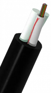 Multicom’s G.652D Aerial Self-Supported ASU Fiber Optic Cable has a loose tube structure and water-resistant gel compound to provide crucial protection for the fiber. This Zero Water Peak fiber optic cable offers up to 12 percent more reach and 27 percent greater served area than the leading LWP competitor. ZWP fiber’s lower inherent loss allows higher network design margins, and thus can support more connections and splices than LWP fiber.
For all FTTx applications including campuses and metro applications, ETC’s ZWP fiber can reach more customers, provide greater network design flexibility, and can generate more revenue than LWP fiber – significantly increasing return on investment in network infrastructure.
Fiber Specification Comparison:
| Fiber Type | G.652.A | G.652.B | G.652.C | G.652.D |
| Wavelength Range | 1310-1550nm | 1310-1625nm | 1310-1625nm | 1310-1625nm |
| Maximum Attenuation Coefficient |
1310nm: 0.5dB/km 1550nm: 0.4dB/km |
1310nm: 0.5dB/km 1550nm: 0.35dB/km 1625nm: 0.4dB/km |
1310-1625nm: 0.4dB/km 1382 ±3nm: 0.4dB/km 1550nm: 0.3dB/km |
1310-1625nm: 0.4dB/km 1382 ±3nm: 0.4dB/km 1530-1565nm: 0.3dB/km |
| Application | 10G, 40G, 10 up to 40km | Higher bit rate applications 10G | Similar to G.652.A Transmission bands can extend to E, S & L. Suitable for CWDM systems |
Similar to G.652.B Transmission bands can extend to E & S. Suitable for CWDM systems |
Bands (wavelengths) – See the graph above
- E band – Refers to the wavelength reach from 1360 – 1460nm
- S-band – Refers to the wavelength reaching from 1460 – 1530nm
- C band – Refers to the wavelength reach from 1530 – 1565nm
- L band – Refers to the wavelength reach from 1565 – 1625nm