

Let’s Get Up to Speed…
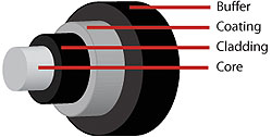
Fiber Optics is sending signals down hair-thin strands of glass or plastic fiber. The light is “guided” down the center of the fiber called the “core”. The core is surrounded by a optical material called the “cladding” that traps the light in the core using an optical technique called “total internal reflection.”
The core and cladding are usually made of ultra-pure glass. The fiber is coated with a protective plastic covering called the “primary buffer coating” that protects it from moisture and other damage. More protection is provided by the “cable” which has the fibers and strength members inside an outer covering called a “jacket”.
Single Mode Fiber Optic Cable
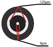 Single Mode fiber optic cable has a small diametral core that allows only one mode of light to propagate. Because of this, the number of light reflections created as the light passes through the core decreases, lowering attenuation and creating the ability for the signal to travel further. This application is typically used in long distance, higher bandwidth runs by Telcos, CATV companies, and Colleges and Universities.
Multimode Fiber Optic Cable
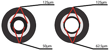 Multimode fiber optic cable has a large diametral core that allows multiple modes of light to propagate. Because of this, the number of light reflections created as the light passes through the core increases, creating the ability for more data to pass through at a given time. Because of the high dispersion and attenuation rate with this type of fiber, the quality of the signal is reduced over long distances. This application is typically used for short distance, data and audio/video applications in LANs. RF broadband signals, such as what cable companies commonly use, cannot be transmitted over multimode fiber.
What’s Happening Inside The Multimode Fiber
Step-Index Multimode Fiber
Due to its large core, some of the light rays that make up the digital pulse may travel a direct route, whereas others zigzag as they bounce off the cladding. These alternate paths cause the different groups of light rays, referred to as modes, to arrive separately at the receiving point. The pulse, an aggregate of different modes, begins to spread out, losing its well-defined shape. The need to leave spacing between pulses to prevent overlapping limits the amount of information that can be sent. This type of fiber is best suited for transmission over short distances.
Graded-Index Multimode Fiber
Contains a core in which the refractive index diminishes gradually from the center axis out toward the cladding. The higher refractive index at the center makes the light rays moving down the axis advance more slowly than those near the cladding. Due to the graded index, light in the core curves helically rather than zigzag off the cladding, reducing its travel distance. The shortened path and the higher speed allow light at the periphery to arrive at a receiver at about the same time as the slow but straight rays in the core axis. The result: digital pulse suffers less dispersion. This type of fiber is best suited for local-area networks.