
Imagine turning a dirt road into a multilane highway without having to perform any new construction. That is what Wave Division Multiplexing (WDM) allows with an existing fiber network. This technology can greatly reduce the cost of increasing network capacity without having to move a single shovelful of dirt or hang a single new fiber.
WHY WDM?
It’s no secret that outside-plant (OSP) fiber construction is expensive. Construction costs vary, but they are always hefty, and they increase greatly if cable is buried. In addition to construction, the costs of permitting, zoning, raw materials and splicing are significant. Thus, avoiding installing new fiber is best whenever possible.
Many communications providers are experiencing fiber exhaust in their networks. This means that the cable counts initially deployed are not able to handle today’s needs. Now, emerging technologies in cell backhaul, business class services and others are creating a need for yet more fibers. However, in most cases, ever-increasing labor and material prices make new fiber construction too costly to consider for many projects.
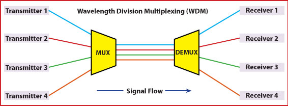
WDM allows operators to place new equipment at either end of a fiber strand and combine multiple wavelength channels on a single fiber strand. Many existing systems use only a small amount of the spectrum available on single piece of glass. Using either coarse wave-division multiplexing (CWDM) or dense wave-division multiplexing (DWDM), operators can combine many different services on a single fiber by assigning a different color, or wavelength, to each service. Multiplexers are used to combine all these wavelengths onto a single fiber, and demultiplexers are used to separate the colors farther on in the network.
Mobile devices, cloud computing, over-the-top video, DOCSIS 3.1 with IPTV, and online gaming are just a few of the drivers for increased bandwidth demand. As demand continues to rise, service providers will need long-term strategies to develop a bigger pipe.
Cellular backhaul, FTTx and commercial business services are also creating a need for more fiber capacity. 3G and 4G cellular services require more bandwidth than cellular services needed in years past and therefore require a fiber link to each cell site. A provider may own a fiber sheath that runs right past a cell tower, but all its fibers may currently be used to maximum capacity. Providing lit services or dark fiber to cell towers can be very profitable but not if it requires plowing or hanging new fiber to these cell sites.
Business-class services are becoming popular revenue sources for communications companies. Businesses are often willing to sign long-term contracts and pay more than residential customers. In some cases, businesses require fiber to meet their bandwidth needs. The same issue arises here: How is it possible to serve these new customers without having to install new OSP fiber to those sites?
WDM TO THE RESCUE
Most legacy fiber networks use a single wavelength, or color, on each fiber. Think of it as two people on different mountaintops using white-lens flashlights to communicate via Morse code – not very sophisticated, but it works.
All of a sudden, two more people want to start communicating between those two mountaintops. What is the solution? Use different colored lenses on the flashlights to communicate. Senders and receivers will recognize and send only their own colors of light and ignore the others.
This is basically what a WDM network does. It uses multiple colors of light over the same medium (fiber). Transmitters tuned to specific wavelengths send light into a passive combiner called a mux (short for multiplexer). All the wavelengths travel down the common fiber and are separated using a passive demultiplexer (also called a demux). Now each receiver at the other end will be able to receive just its own discrete signal.
In other words, WDM maps multiple optical signals to individual wavelengths and multiplexes the wavelengths over a single fiber. WDM can carry multiple protocols without having to convert them to a common signal format. A single fiber is able to do virtually anything that’s needed.
There are two main types of WDMs. The advantage of CWDM technology is that it is relatively inexpensive compared with DWDM. The transmitters used in CWDM are less expensive, as they do not need to be tuned as precisely as DWDM transmitters. However, CWDM has drawbacks, too: Only 18 channels are available, and fiber amplifiers cannot be used with them. Thus, they are not the ideal choice for long-haul networks.
CWDM channels each consume 20 nm of space and together use up most of the single-mode operating range. The wavelengths most commonly used are the eight channels in the 1470 to 1610 nm range. Any transceiver used in CWDM applications operates within one of these channels.
DWDM allows many more wavelengths to be combined onto one fiber. It also leverages the capabilities of fiber amplifiers, which can amplify the 1550 nm or C band commonly used in DWDM applications. This makes it ideal for use in long haul and areas of greater customer density. Instead of the 20 nm spacing in CWDM (equivalent to about 15 million GHz), DWDM uses either 50, 100 or 200 GHz spacing in the C and sometimes the L bands. This allows many more wavelengths to be packed onto the same fiber.
The downside of DWDM is that the lasers need to be much more accurate and require precise temperature ranges to operate. This makes DWDM applications much more expensive than CWDMs. The introduction of the ITU-T G.694.1 grid in 2002 made integrating DWDM technology easier. It created an industry standard for DWDM.
CHOOSING A TYPE OF WDM
Before deploying any WDM equipment, it is necessary to ensure that the glass in place will support all the required wavelengths. Low-water-peak or zero-water-peak fiber is more suitable for WDM applications, and older glass types may have water peak issues. If the glass is too old, it may be necessary to bite the bullet and install some new fiber.
Assuming the glass is appropriate for WDM, should you use CWDM or DWDM technology to solve fiber exhaust problems? As previously noted, CWDM can support a maximum of 18 channels and is not ideal for long haul. So CWDM would typically be best for applications that do not require the signal to travel great distances and in locations where not many channels are required. The availability of SFP transceivers may also be a limiting factor.
For applications that require a high number of channels or for long-haul applications, DWDM is the ideal solution. Though the electronics and passives are not cheap, they are considerably more cost-effective than putting in new fiber.
DESIGN CONSIDERATIONS
It’s important to ensure that the CWDM and DWDM passives will operate properly in the environment where they will be placed. This becomes especially important when putting CWDM passives in the outside plant. Before buying a mux or demux for use in an unconditioned cabinet or splice case, verify that the operating temperature will fit the application. Many vendors specify the storage temperature but not the operating temperature.
The operating temperature of an optical component is the actual temperature range in which the component will work. Usually, a component must remain within a specified temperature range to perform at a specified optical performance level.
The storage temperature of an optical component is the temperature at which an optical component can be stored without causing any degradation or component failure when it is used in the component’s specified operating temperature limits. Some storage temperatures can exceed the actual operating temperature of the components. When sourcing WDM filters, ensure that they will be able to operate within the temperatures in which they will be deployed.
Another design consideration with any WDM network is insertion loss. Though WDM creates a huge increase in capacity, it also creates insertion loss in a network. Using the maximum insertion loss values in the link budget is a good idea; keep in mind that some manufacturers do not include the connector loss if the device is terminated.
Calculate the loss for both the mux and demux components. The maximum insertion loss on a typical eight-channel CWDM is 3 dB, so for a mux/demux solution, add 6 dB of insertion loss.
WDM filters can be designed to drop individual colors at a specific location and keep sending the rest down the fiber path. In some applications, combining several wavelengths at a certain location and then dropping individual channels to customers along the same route may be desirable. This is the most common type of design used in fiber-to-the business and cell tower applications.
SUMMARY
WDM technology is a very effective method for overcoming fiber exhaust. Placing passive filters and WDM transceivers at each end of a fiber optic network can greatly increase bandwidth without having to spend capital on new fiber construction projects. Most current fiber technologies use only a small sliver of the available bandwidth capacity of single-mode glass, so a properly designed WDM network can unlock a floodgate of available power in a network. Using many channels on the same piece of optical fiber enables operators to serve businesses, cell towers and residential customers with the same fiber. Fiber counts are no longer a constraint.
Article Credit: Tom Warren, Clearfield Application Engineer